PiPower: A Raspberry Pi UPS
I have a Raspberry Pi running RetroPie hooked up to a television. It’s powered from a USB port on the TV, which is convenient, but it means that whenever we shut off the TV we’re pulling the plug on the Pi. While there haven’t been any problems so far, this is a classic recipe for filesystem problems or data loss at some point. I started looking into UPS options to alleviate this issue. I wanted something with the following features:
- Notify the Pi when external power is removed so that the Pi can shut down cleanly.
- Power off the Pi after the Pi has shut down.
- Boot the Pi when external power is restored.
There are several Pi UPS solutions out there, but most of them are designed for a different purpose: they will run your Pi from battery for as long as possible, and will notify your Pi when the battery level goes low. That’s great if you want a portable device, but isn’t the right solution for my situation. One notable exception is the juice4halt product, which is a super-capacitor based unit that does pretty much exactly when I want. Unfortunately, it is somewhat pricey.
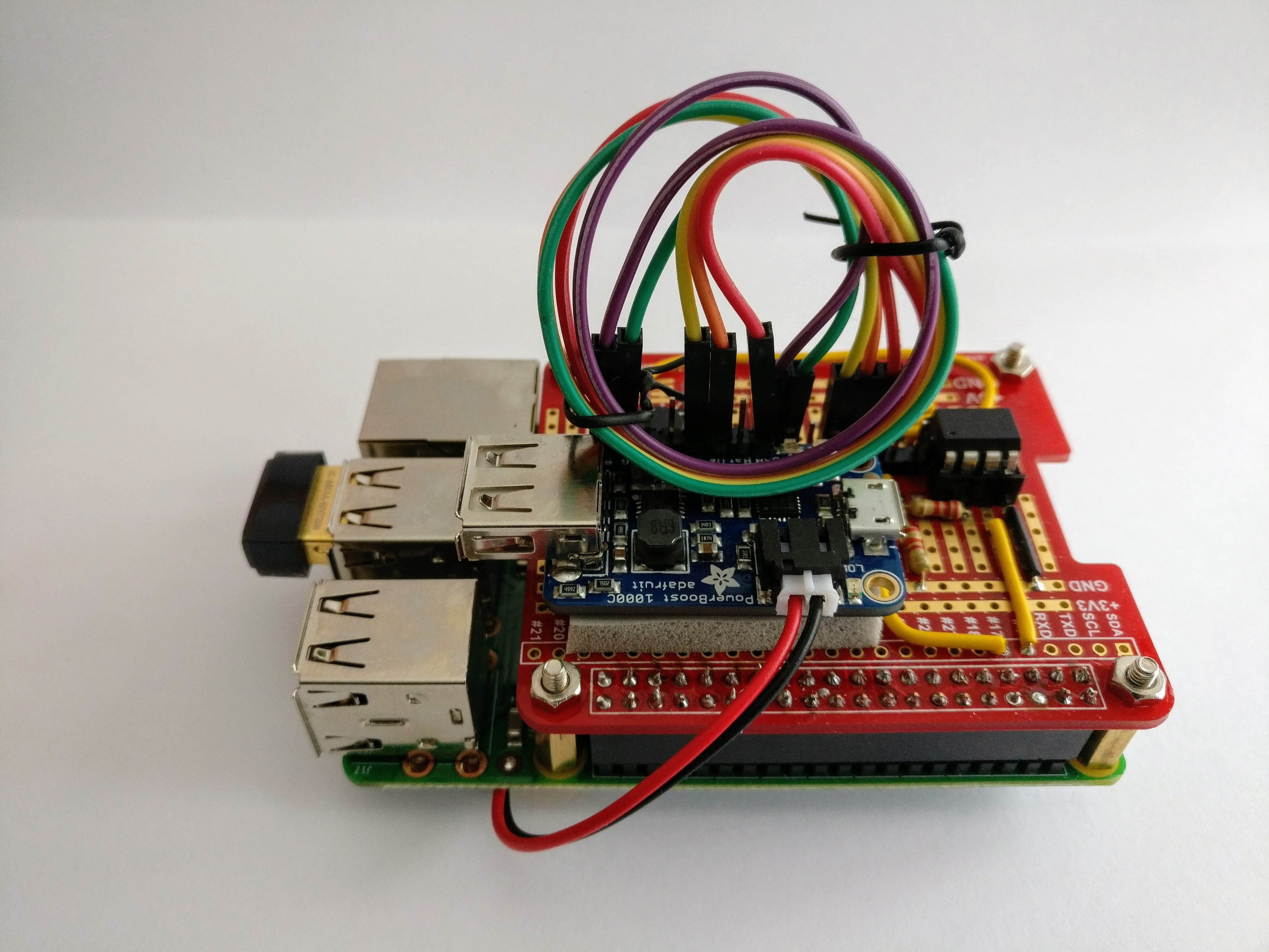
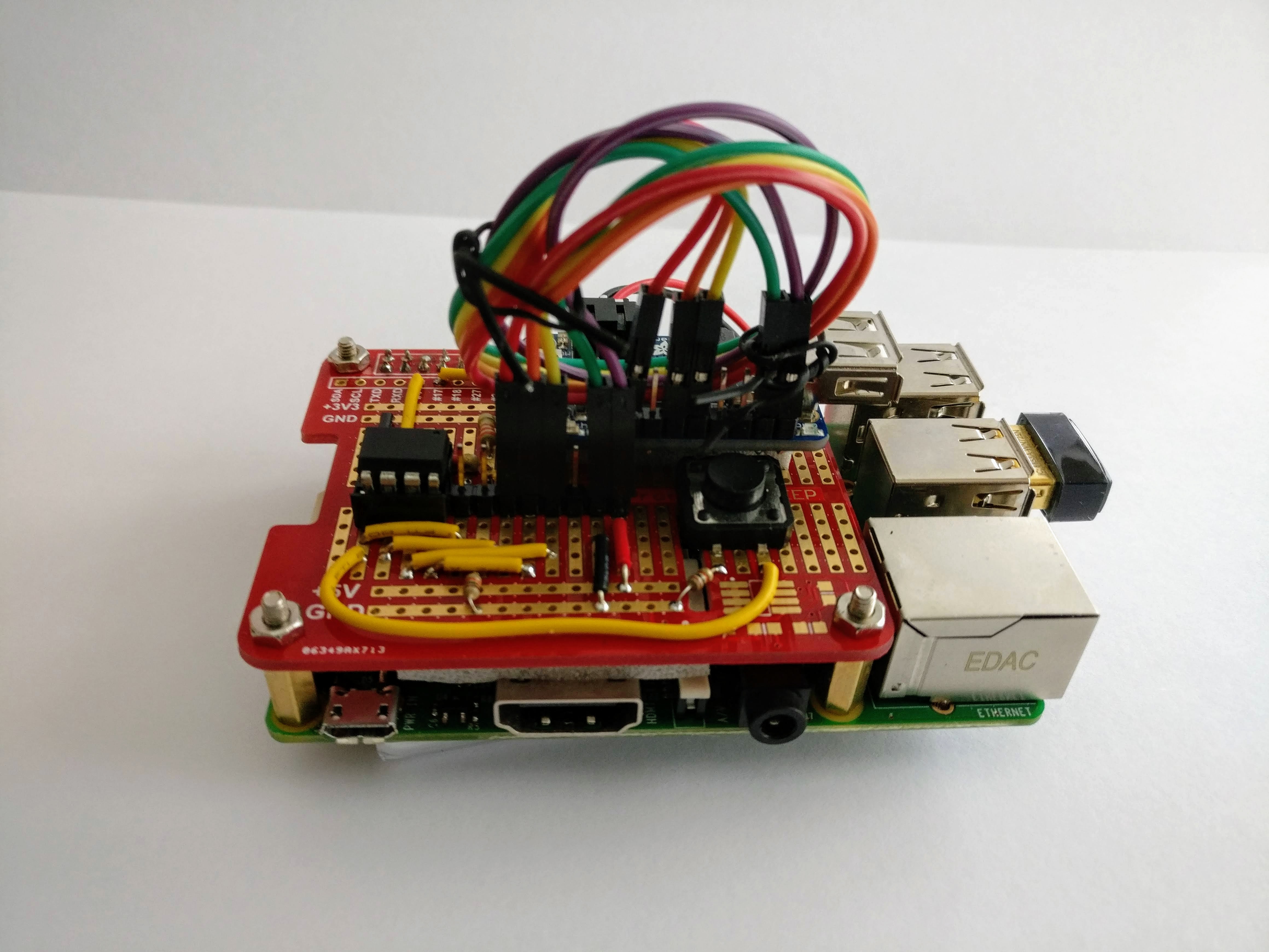
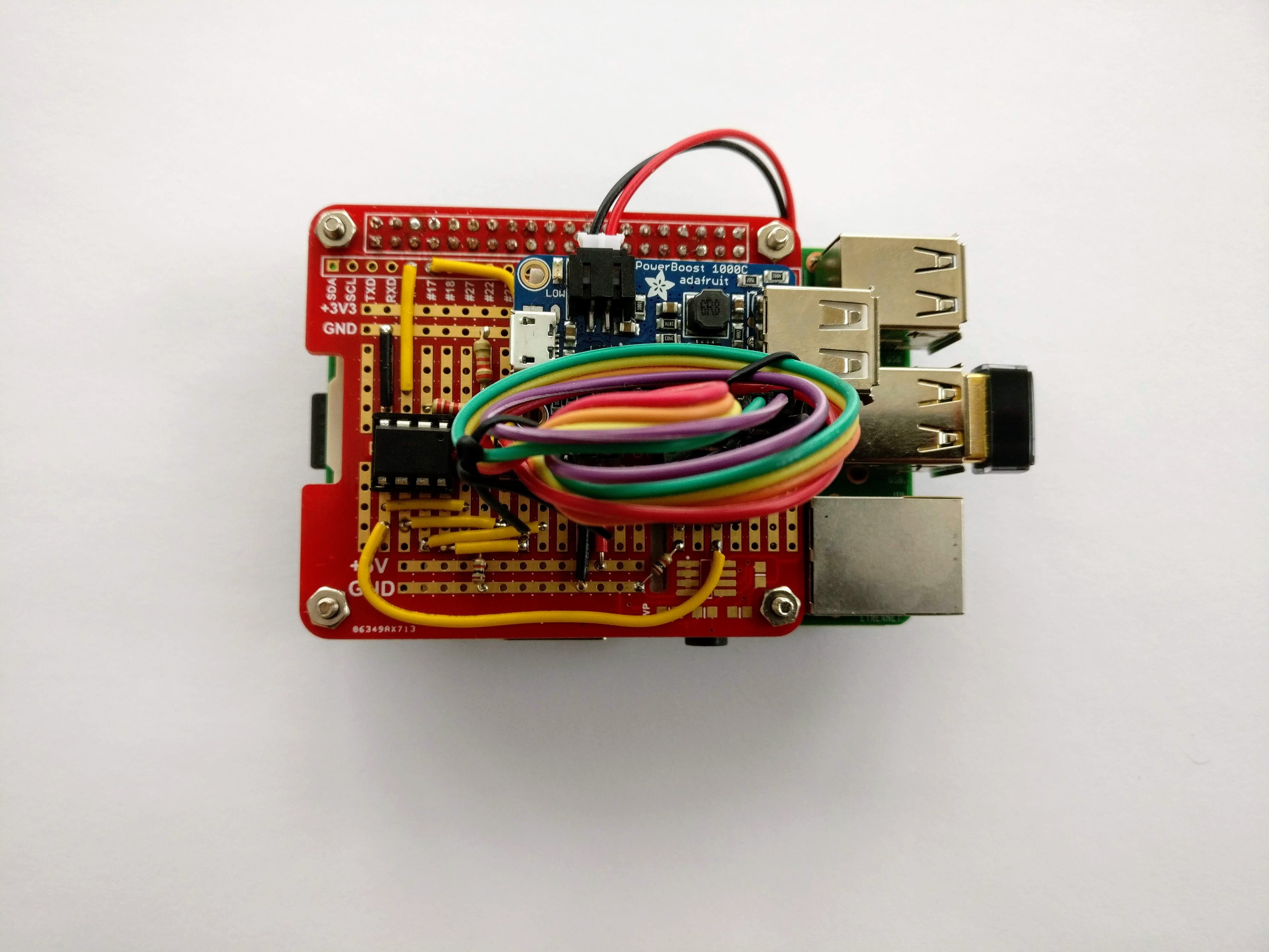
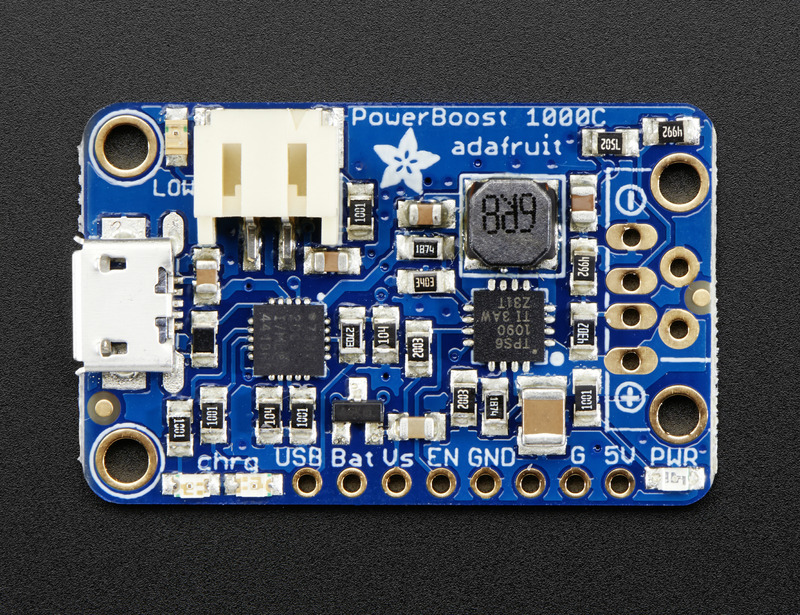
While looking at various solutions, I found the Adafruit PowerBoost 1000c. When external power is available, this device will charge a LIPO battery and provide power to your Pi at the same time. When external power is removed, this device will power your Pi from the battery. By itself it doesn’t have any facilities for communicating with your Pi, but it does provide several control lines which suggested some interesting possibilities.
Getting the Powerboost talking to the Pi seemed like a good job for a small microcontroller. I happen to have a few attiny85s kicking about, so I decided to use one of those.
Code⌗
You can find all the code used in this project in the GitHub repository. The code is written in C, and can be compiled using avr-gcc. It requires avr-libc.
Theory of operation⌗
When everything first boots up, the microcontroller checks the USB signal from the PowerBoost to see if external power is available. The USB line must remain high for 1 second before it is considered valid (it turns out that the USB can go high momentarily when things first come on, so this avoids erroneously powering up the Pi when external power isn’t available).
If power is available, the controller brings the EN line high, which causes the PowerBoost to start supplying power to the Pi. The controller will wait for up to 30 seconds for the BOOT line to go low. The Pi boots up, and the pipower-up service (see below) brings the BOOT line low to indicate that it has successfully booted. If the BOOT line does not go low within 30 seconds, the controller assumes the Pi has failed to boot and disconnects the power, then enters the lower-power idle mode.
If you shut down the Pi manually, the pipower-up service will set the BOOT line high late in the shutdown sequence to indicate that the Pi is shutting down. The microcontroller will wait an additional 30 seconds and will then turn off power to the Pi. If the BOOT line goes low again during this time (e.g, if you rebooted the Pi instead of shutting it down), the microcontroller will cancel the shutdown.
If while the Pi is running you press the power button on the board, this will set the SHUTDOWN line high. The pipower-down service will respond to this signal by starting a clean shut down. The controller will wait up to 30 seconds for the Pi to set the BOOT line high, at which point it will wait another 30 seconds before removing power.
If while the Pi is running external power is removed, the microcontroller will set the SHUTDOWN line high, and will follow the same logic as if you had pressed the power button.
If the microcontroller is in the idle state and external power is available, you can press the power button to boot the Pi. If external power is not available, then applying external power will cause the Pi to boot.
At any point, a long press (two seconds ore more) of the power button will immediately remove power from the Pi and place the controller in the idle state.
Notes on the code⌗
I initially started writing the code using the Arduino IDE, but I decided to switch to avr-gcc early on because I found that easier to work with. Since various aspects of the code require tracking the passage of time, the first thing I had to do was implement a version of the millis() function. You can see my implementation in millis.c. This uses TIMER0 on the attiny85 with a divider of 64 (TCCR0B = 3<<CS00), since that should allow the code to work with processor running at 16Mhz.
I wrote debouncing code for the power button using the mechanism described by Elliot Williams in “Debounce your Noisy Buttons, Part II”. I wrote an object-oriented implementation that you can find in button.c.
Most of the implementation logic can be found in the state machine implemented as a switch statement in lines 125-254 of pipower.c.
I have documented the code using Doxygen. If you have Doxygen installed, you can cd docs and run make to create the code documentation.
pins⌗
The attiny85 only has 5 available pins (6, if you’re either very confident or have a high voltage programmer available). I ended up setting things up like this:
PB0- connected to a momentary-contact switchPB1- connected toUSBsignal from the powerboostPB2- connected to theENsignal to the powerboostPB3- connected to theSHUTDOWNsignal to the PiPB4- connected to theBOOTsignal from the PiVCC- connected to theVsoutput from the powerboost
I am intentionally not using the low battery (LBO) signal, since I’m not trying to run the Pi off the battery for an extended period of time. If I build or acquire a high voltage programmer, I might wire LBO to PB5, or just connect the BAT signal and use PB5 as an analog Pin, and trigger a shutdown on a low-battery condition as well.
systemd units⌗
The only software required on the Raspberry Pi is wiringPi, a library and toolset for manipulating GPIO on your Raspberry Pi, and the following systemd units. If you are building this yourself and disagree with my pin selections, you can create the file /etc/default/pipower and set one or both of PIN_SHUTDOWN and PIN_BOOT to BCM GPIO pins of your choice.
pipower-up⌗
At boot, the pipower-up service configures PIN_BOOT (defaults to BCM GPIO 4) as an output and then brings it low. This notifies the code running on the attiny85 that the Pi has successfully booted. When the Pi shuts down, the unit sets PIN_BOOT high, which notifies the controller that the Pi is about to shut down.
This service is designed to run early in the boot process and late in the shutdown process.
[Unit]
Description=[pipower] Assert BOOT signal
DefaultDependencies=no
After=final.target systemd-journald.service

[Service]
Type=oneshot
Environment=PIN_BOOT=4
EnvironmentFile=-/etc/default/pipower
RemainAfterExit=true
ExecStartPre=/usr/bin/gpio -g mode $PIN_BOOT output
ExecStart=/usr/bin/gpio -g write $PIN_BOOT 0
ExecStopPost=/bin/sh -c "test -f /run/pipower/inhibit || /usr/bin/gpio -g write $PIN_BOOT 1"

[Install]
WantedBy=multi-user.target
pipower-down⌗
At boot, the pipower-down service configures PIN_SHUTDOWN (defaults to BCM GPIO 17) as an input w/ the pulldown resistor enabled. It then uses the gpio command to wait for a rising interrupt on PIN_SHUTDOWN; when it receives one, it calls systemctl poweroff to cleanly shut down the system.
[Unit]
Description=[pipower] Monitor SHUTDOWN signal

[Service]
Type=simple
Environment=PIN_SHUTDOWN=17
EnvironmentFile=-/etc/default/pipower
ExecStartPre=/usr/bin/gpio -g mode $PIN_SHUTDOWN input
ExecStartPre=/usr/bin/gpio -g mode $PIN_SHUTDOWN down
ExecStart=/usr/bin/gpio -g wfi $PIN_SHUTDOWN rising
ExecStopPost=/bin/sh -c "test -f /run/pipower/inhibit || /bin/systemctl poweroff"

[Install]
WantedBy=multi-user.target
Caveats⌗
The PowerBoost 1000c does not provide adequate power for a Raspberry Pi 3B+. It seems to be just adequate for a Pi 2B.
If you stop either of the systemd units, your Pi will either shutdown (if you systemctl stop pipower-down) or will simply lose power (if you systemctl stop pipower-up). You can inhibit the ExecStop* actions of both units by creating the file /run/pipower/inhibit.
TODO⌗
With a few more pins available – maybe an attiny84 – it might be fun to provide battery voltage and current measurements to the Pi via an i2c interface. I would probably also add a status LED to show the current state of the controller code.